Chapter 8
Communication Interfaces Real-Time Embedded Systems for AI
8. Communication Interfaces Real-Time Embedded Systems for AI [5 hrs]
Wired Communication Medium (RS232/UART, USB, Ethernet) for AI Data Transfer
Wireless Communication Medium (Infrared, IEEE 802.11, Bluetooth) for AI Systems
Real-Time Operating Systems for AI Applications
Scheduling Algorithms for Real-Time AI Tasks
Need for Communication Interfaces
Why are Communication Interfaces Required in Embedded Systems?
- Need to send data to a host. The host will analyze of data and present the data through a Graphical User Interface.
- Need to communicate with another embedded system to transmit / receive data.
- Need to be networked to share data. Network interfaces need to be provided in such a case.
- Need to be connected to the Internet so that anyone can access the embedded system.
- Mobile devices such as cell phones and palmtops need to interact with other devices such as PCs and laptops for data synchronization.
- Need of s/w upgradation after it is installed in the field. The software can be upgraded through communication interfaces.
Embedded Communication

8.1 Wired Communication Medium (RS232/UART, USB, Ethernet) for AI Data Transfer
Learning Objectives
- Define wired communication and explain its importance in embedded AI systems.
- Describe the working principles of RS232/UART, USB, and Ethernet communication interfaces.
- Compare RS232/UART, USB, and Ethernet based on speed, distance, reliability, and applications.
- Identify appropriate wired communication interfaces for different AI data transfer requirements.
- Explain how wired communication enables reliable data exchange between embedded AI devices and external systems.
RS232/UART
- RS232 is a standard developed by the Electronic Industries Association (EIA).
- It is one of the oldest and most widely used communication interfaces.
- A personal computer (PC) typically has two RS232 ports designated as COM1 and COM2.
- Most microcontrollers provide an on-chip UART (Universal Asynchronous Receiver/Transmitter) serial interface.
- Processor evaluation boards are commonly connected to a host computer using the RS232 interface.
- RS232 is used to connect a Data Terminal Equipment (DTE) to a Data Circuit-Terminating Equipment (DCE).
- DTE Examples: PC, serial printer, plotter.
- DCE Examples: Modem, mouse, digitizer, scanner.
- RS232 specifies only the physical layer interface for serial communication.
- It is a serial communication standard, where data bits are transmitted one after another.
- Communication is full duplex, allowing simultaneous data transmission in both directions.
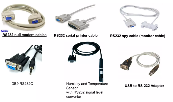
RS232 Serial Connector
UART Serial Communication
RS232 Communication Parameters
- In RS232 communication, the transmitting device sends data character by character.
- The binary representation of each character is known as the data bits.
- A Start Bit is transmitted before the data bits to indicate the beginning of a character.
- One or two Stop Bits are transmitted after the data bits to indicate the end of the character.
- The receiving device uses the Start Bit and Stop Bit to correctly identify and decode the incoming data.
- RS232 uses asynchronous communication, meaning that no separate clock signal is transmitted between devices.
- An optional Parity Bit may be included between the data bits and stop bit(s).
- The Parity Bit provides a simple method of error detection at the receiving end.
RS232 Data Frame: Start Bit → Data Bits → Parity Bit → Stop Bit(s)
RS232 Communication Parameters
- Both communicating devices must be configured with identical communication parameters for successful RS232 communication.
- Data Rate (Baud Rate)
- Determines the speed of data transmission.
- Measured in bits per second (bps).
- Common baud rates: 50, 150, 300, 600, 1200, 2400, 4800, 9600, 19200, 38400, 57600, 115200 bps.
- Data Bits
- Represents the number of bits used for each transmitted character.
- Possible values: 5, 6, 7, or 8 bits.
- ASCII characters typically use 7 data bits.
RS232 devices must use identical communication settings.
| Parameter | Example |
|---|---|
| Baud Rate | 9600 bps |
| Data Bits | 8 |
RS232 Data Transfer Process
Transmitter (DTE)
PC / Microcontroller
Receiver (DCE)
Modem / Device
RS232 Communication Parameters (Continued)
-
Start Bit
- Prefixed before the data bits.
- Identifies the beginning of a character.
-
Stop Bits
- Appended after the data bits.
- Indicates the end of the character.
- If data bits are 7 or 8 → 1 Stop Bit.
- If data bits are 5 or 6 → 2 Stop Bits.
-
Parity Bit
- Used for error detection.
- Can be Even, Odd, or None.
- Example Data: 1010110
- Even Parity → Parity Bit = 0
- Odd Parity → Parity Bit = 1
- The receiver recalculates the parity to detect transmission errors.
| Pin No. | Abbreviation | Full Form / Function |
|---|---|---|
| 1 | CD | Carrier Detect |
| 2 | RXD | Receive Data |
| 3 | TXD | Transmit Data |
| 4 | DTR | Data Terminal Ready |
| 5 | GND | Signal Ground |
| 6 | DSR | Data Set Ready |
| 7 | RTS | Request To Send |
| 8 | CTS | Clear To Send |
| 9 | RI | Ring Indicator |
DTE and DCE Devices
- DTE (Data Terminal Equipment) is the source or destination of data.
- Examples:
- Desktop Computer
- Laptop
- Microcontroller Board
- Serial Terminal
- DCE (Data Circuit-Terminating Equipment) provides the communication interface.
- Examples:
- Modem
- Scanner
- Industrial Controller
- Communication Device
- RS232 defines communication between a DTE and a DCE.
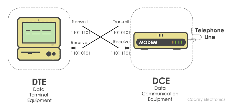
Typical RS232 Communication between DTE and DCE
RS232 Flow Control (Handshaking)
- When one device transmits data faster than the receiving device can process it, Flow Control is required.
- Flow Control temporarily stops and resumes data transmission to prevent data loss.
- This mechanism is also known as Handshaking.
-
Hardware Handshaking
- Uses two control signals:
- RTS (Request To Send)
- CTS (Clear To Send)
- The sender asserts RTS; the receiver responds with CTS when ready.
-
Software Handshaking (XON/XOFF)
- Ctrl + S (0x13) → Suspend transmission (XOFF).
- Ctrl + Q (0x11) → Resume transmission (XON).
Hardware and Software Flow Control
| Method | Signal |
|---|---|
| Hardware | RTS / CTS |
| Software | XON / XOFF |
RS232 Voltage Levels
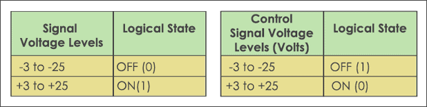
- Unlike TTL logic (0V and +5V), RS232 uses positive and negative voltages to represent binary values.
- Logic 1 (MARK)
- Voltage between -3V and -15V.
- Logic 0 (SPACE)
- Voltage between +3V and +15V.
- Voltages between -3V and +3V are considered an undefined region.
- Because of these voltage levels, a level converter (e.g., MAX232) is required to connect microcontrollers to RS232 devices.
MAX232 converts TTL voltage levels to RS232 voltage levels.
RS232 Communication Interface
- RS232 defines communication between Data Terminal Equipment (DTE) and Data Circuit-Terminating Equipment (DCE).
- The standard uses D-subminiature (D-Sub) connectors for physical connections.
- The two most common connector types are:
- DB9 (9-pin connector)
- DB25 (25-pin connector)
- Both connectors are available in Male and Female versions.
- Each pin has a specific communication or control function, such as transmitting data, receiving data, handshaking, or grounding.
- Modern computers typically use the DB9 connector, while older systems often used the DB25 connector.
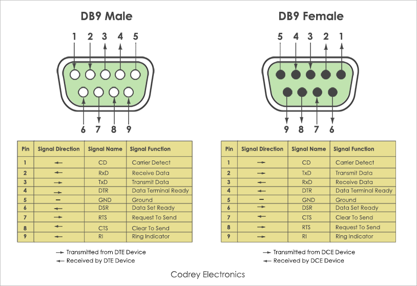
D-Sub Connectors: DB9 and DB25 (Male and Female)
| Connector | Pins |
|---|---|
| DB9 | 9 |
| DB25 | 25 |
UART (Universal Asynchronous Receiver/Transmitter)
- Processors work with parallel data, whereas RS232 transmits data in serial format.
- RS232 also uses higher positive and negative voltage levels, which are different from the low-voltage logic levels (3.3V/5V) used by most embedded systems.
- These differences are overcome using a UART (Universal Asynchronous Receiver/Transmitter).
- UART has two sections:
- Receive Section (RX): Converts serial data into parallel data for the processor.
- Transmit Section (TX): Converts parallel data from the processor into serial data.
- UART automatically generates the Start Bit, Parity Bit, and Stop Bit(s).
- Most modern microcontrollers include an on-chip UART.
- A level shifter (e.g., MAX232) is still required to convert UART voltage levels to RS232 voltage levels.
RS232 vs UART
| Feature | RS232 | UART |
|---|---|---|
| Definition | Communication standard | Hardware module for serial communication |
| Voltage Level | ±3V to ±15V | TTL/CMOS (0–3.3V or 0–5V) |
| Signal Type | Standardized interface | TX and RX logic signals |
| Distance | Up to 15 m (typical) | Short PCB connections |
| Converter Required | No | Needs MAX232 to connect to RS232 |
Key Point: UART generates serial data, while RS232 defines how that data is electrically transmitted.
Advantages of RS232
- Simple and inexpensive communication interface.
- Easy to implement using built-in UART peripherals.
- Reliable for short-distance communication.
- Supports full-duplex communication.
- No clock synchronization required (asynchronous communication).
- Widely supported by industrial equipment and laboratory instruments.
- Suitable for debugging, configuration, and firmware updates.
RS232 remains widely used in industrial systems.
Limitations of RS232
- Limited communication distance (approximately 15 m).
- Lower data rate compared to USB, Ethernet, and CAN.
- Point-to-point communication only.
- Poor noise immunity over long cables.
- Large voltage levels require level-shifting circuits.
- Modern laptops usually do not include native RS232 ports.
- Not suitable for high-speed networking applications.
Level shifters are required for microcontroller interfaces.
Applications of RS232
- Communication between PCs and microcontrollers.
- Industrial automation and PLC programming.
- Serial console for embedded Linux systems.
- GPS receivers and navigation devices.
- Point-of-sale (POS) terminals.
- Medical and laboratory instruments.
- Network switches, routers, and embedded debugging.
- Firmware downloading and device configuration.
RS232 console cable used for configuring networking equipment.
RS422 and RS485 Communication Standards
- RS422 and RS485 are serial communication standards developed to overcome the distance and speed limitations of RS232.
- RS422
- Uses differential signaling for improved noise immunity.
- Supports one transmitter and multiple receivers (up to 10).
- Communication distance up to 1200 m.
- Data rate up to 10 Mbps (short distance).
- RS485
- Uses differential signaling.
- Supports multiple transmitters and multiple receivers (multi-drop network).
- Allows up to 32 devices (or more with modern transceivers).
- Widely used in industrial automation, PLCs, and Modbus networks.
- Advantages over RS232: Longer distance, higher speed, better noise immunity, and multi-device communication.
Universal Serial Bus (USB)
- Universal Serial Bus (USB) is one of the most widely used communication interfaces for connecting peripheral devices to computers.
- Common USB-enabled devices include:
- Desktop and Laptop Computers
- Printers and Scanners
- Display Devices
- Video Cameras
- External Hard Disk Drives
- Audio Equipment
- USB follows a Master/Slave architecture, where:
- The Host (Master) is typically a PC.
- Peripheral devices act as USB Devices (Slaves).
- The host contains a USB Host Controller (hardware + software) that manages communication with all connected USB devices.
- USB devices can be connected:
- Directly to the host.
- Through a USB Hub, which expands the number of available ports (typically 2–8 ports).
- USB devices may be:
- Self-powered
- Bus-powered (powered directly by the USB cable).
- A standard USB port can supply up to 500 mA of current to connected devices.
USB Hub expands the number of available USB ports
USB Physical Interface
- USB uses a shielded 4-wire twisted copper cable for communication and power delivery.
- The four wires in a standard USB cable are:
- VBUS – +5 V Power Supply
- D+ – Positive Differential Data Line
- D− – Negative Differential Data Line
- GND – Ground
- Data is transmitted using a differential twisted pair consisting of the D+ and D− wires.
- Differential signalling provides:
- Better noise immunity
- Higher data integrity
- Reliable communication over longer cables
- The outer shield minimizes electromagnetic interference (EMI).
USB Type-A Connector Pinout
Features of USB
-
Data Rates
- USB 1.1
- 12 Mbps (Full Speed)
- 1.5 Mbps (Low Speed)
- USB 2.0
- Up to 480 Mbps (High Speed)
- USB 1.1
-
Plug and Play
- Devices are automatically detected.
- No manual hardware configuration required.
-
Bus Enumeration
- The host exchanges packets with the device.
- Identifies the device and configures communication.
-
Hot-Pluggable
- Devices can be connected or removed while the computer is running.

USB Host automatically detects connected devices.
| USB Version | Maximum Speed |
|---|---|
| USB 1.1 | 12 Mbps |
| USB 2.0 | 480 Mbps |
USB Communication Protocol and Device Classes
-
Packet-Based Communication
- Communication occurs through data packets.
- The host obtains the device configuration and properties.
- Each connected device is assigned a unique ID (1–127).
-
Host Responsibilities
- Detect newly connected devices.
- Assign device addresses.
- Exchange control and data packets.
- Receive notification when a device is removed.
-
USB Packets
- Short packets are used for handshaking and acknowledgements.
- Data packets can contain up to 1023 bytes.
| Common USB Device Classes | |
|---|---|
| 🖥 | Display |
| 🌐 | Communication |
| 🎵 | Audio |
| 💾 | Mass Storage |
| ⌨️ | Human Interface Devices (HID) |

USB devices are automatically identified and classified.
Ethernet Interface in Embedded Systems
- Ethernet is one of the most widely used wired communication technologies for computer networks.
- It is available on almost every desktop and laptop computer.
- The availability of low-cost Ethernet controllers (chips) and the TCP/IP protocol stack makes Ethernet easy to implement in embedded systems.
- An embedded system with an Ethernet interface can be connected directly to a Local Area Network (LAN).
- Sensor readings and other data collected by the embedded system can be transferred to a server or database on the LAN.
- Ethernet provides the Physical Layer and Data Link Layer services of the OSI model.
- Higher-level communication is achieved using TCP/IP and Application Layer Protocols (e.g., HTTP, FTP, MQTT).

Ethernet operates at the Physical and Data Link Layers.
Ethernet Physical Layer
- The Physical Layer of Ethernet defines how devices are physically connected to a Local Area Network (LAN).
- Ethernet commonly uses an RJ45 connector (8P8C) for network connections.
- Transmission media include:
- Unshielded Twisted Pair (UTP) cable
- Coaxial cable (legacy Ethernet)
- Ethernet uses differential signalling:
- One wire carries signals from 0 V to +2.5 V.
- The second wire carries signals from −2.5 V to 0 V.
- The voltage difference between the pair is approximately 5 V.
- Common Ethernet speeds supported:
- 10 Mbps (10BASE-T)
- 100 Mbps (100BASE-TX)
RJ45 Ethernet Connector
Ethernet Data Link Layer
- The Data Link Layer is responsible for reliable communication between devices on the same Local Area Network (LAN).
- It consists of two sublayers:
- Medium Access Control (MAC)
- Logical Link Control (LLC)
- MAC Layer
- Controls access to the shared communication medium.
- Uses the Carrier Sense Multiple Access with Collision Detection (CSMA/CD) protocol.
- Detects collisions and retransmits data when necessary.
- LLC Layer
- Establishes logical communication.
- Provides flow control.
- Performs error control.
- Supports acknowledgements.
- Every Ethernet interface has a unique 48-bit MAC Address.
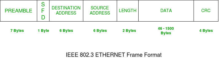
Ethernet Frame and MAC Address
CSMA/CD Medium Access Mechanism
TCP/IP Stack in Embedded Ethernet Systems
- To make an embedded system network-enabled, the TCP/IP protocol stack must run above the Ethernet layer.
- The TCP/IP stack is integrated with:
- Operating System (OS)
- Firmware
- Application Software
- Application protocols provide different network services:
- SMTP – Sending e-mails
- FTP – File transfer
- HTTP – Web server communication
- These protocols enable embedded devices to communicate over LANs and the Internet.
Sensor → Ethernet → TCP/IP → HTTP Server → Web Browser
Sensor → Ethernet → TCP/IP → SMTP → Email Alert
Sensor → Ethernet → TCP/IP → FTP → Data Backup

TCP/IP Protocol Stack
MODM7AE70 ARM Cortex M-7 Embedded IoT Development Kit
8.2 Wireless Communication Medium for AI Systems
Topics Covered
- Introduction to Wireless Communication
- Infrared (IR) Communication
- IEEE 802.11 (Wi-Fi)
- Bluetooth Technology
- Comparison of Wireless Communication Technologies
- Applications in AI and Embedded Systems
Understand the working principles, characteristics, advantages, limitations, and AI applications of Infrared (IR), Wi-Fi (IEEE 802.11), and Bluetooth communication technologies used in modern embedded systems.
Common Wireless Communication Technologies
Introduction to Wireless Communication
- Wireless communication is the transmission of information between devices without using physical cables.
- Data is transmitted through electromagnetic waves such as:
- Radio Waves
- Infrared (IR)
- Microwaves
- Wireless communication enables:
- Mobility
- Remote monitoring
- Real-time data exchange
- Internet of Things (IoT)
- It is widely used in embedded systems, AI devices, smart homes, healthcare, industrial automation, robotics, and autonomous vehicles.
- Common wireless communication technologies include:
- Infrared (IR)
- Wi-Fi (IEEE 802.11)
- Bluetooth
Wireless communication between embedded devices
Wireless technologies use different regions of the electromagnetic spectrum.
Infrared (IR) Communication
- Infrared (IR) is a wireless communication technology that uses infrared light waves to transmit data between devices.
- IR communication is a line-of-sight (LOS) technology, meaning the transmitter and receiver must face each other.
- It is suitable for short-distance communication, typically ranging from a few centimeters to several meters.
- IR communication is immune to radio frequency (RF) interference but can be affected by obstacles and strong sunlight.
- Advantages
- Low cost and low power consumption
- Simple hardware implementation
- Secure due to limited transmission range
- Limitations
- Requires direct line of sight
- Cannot penetrate walls or solid objects
- Limited communication range
Infrared communication requires a clear line of sight.
TV remote controls commonly use Infrared (IR) communication.
Infrared
- IrDA module shows the device with an infrared transceiver.
- The transmitter is an LED and the receiver is a Photodiode.
- For low data rates, the processor of the embedded system itself can be used, whereas for high data rates, a separate processor may be required.
- The data to be transmitted is packetized and encoded according to the IrDA protocol before being sent over the infrared link.
- The receiving device detects the signal, decodes, and depacketizes the received data.
Infrared
- For communication through the Infrared (IrDA) Interface, the IrPHY and IrLAP layers are specified in the standard.
- Link Management is performed by IrLMP, above which the Application Layer Protocols execute.
Applications (IrCOMM, OBEX, etc.)
↓
IrLMP (Link Management)
↓
IrLAP (Link Access)
↓
IrPHY (Infrared Physical Layer)
(Application, IrCOMM)
(IrLMP)
(IrLAP)
(IrPHY)
| Layer | Purpose |
|---|---|
| IrPHY | Physical transmission of infrared light. Defines optical signals, modulation, transmission speed, and receiver sensitivity. |
| IrLAP | Provides reliable link access, device discovery, connection establishment, addressing, and error recovery between two IrDA devices. |
| IrLMP | Manages multiple logical connections, service discovery, and communication between applications over the infrared link. |
| Higher Layers | Application protocols such as IrCOMM, OBEX, printing, synchronization, and file transfer use the services provided by lower layers. |
IR Sensor Module
- The IR Sensor Module is an electronic sensor used for obstacle detection and proximity sensing.
- It works by transmitting infrared light and detecting the reflected light from nearby objects.
- The module mainly consists of:
- IR Transmitter (IR LED)
- IR Receiver (Photodiode)
- LM358 Comparator
- Variable Resistor (Preset)
- Status LED
- Provides a digital HIGH/LOW output for microcontrollers.
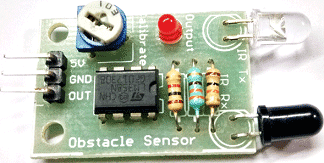
IR Sensor Module
IR Sensor Module Pinout & Features
| Pin | Description |
|---|---|
| VCC | Power Supply Input |
| GND | Ground |
| OUT | Digital Output |
Features
- Operating Voltage: 5 V
- Compatible with 3.3 V and 5 V logic
- Detection Range: Up to 20 cm
- Adjustable sensing distance
- Built-in Ambient Light Filter
- Supply Current: 20 mA
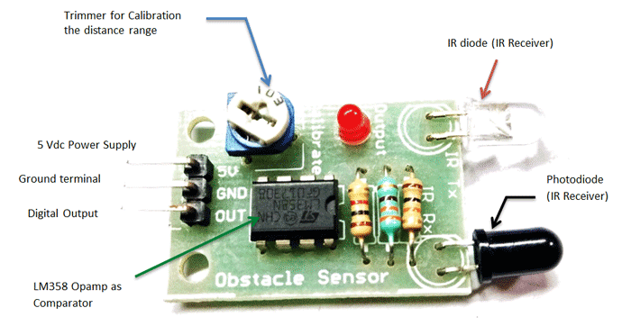
IR Sensor Pinout
Working Principle of IR Sensor Module
- IR LED continuously emits infrared light.
- When no object is present, the emitted light does not return to the receiver.
- When an object comes within range, the infrared light is reflected back.
- The photodiode receives the reflected light.
- LM358 Comparator compares the received signal with a preset threshold.
- The module output changes HIGH/LOW and the indicator LED turns ON.
Object Detection using Reflected IR Light
IR Sensor Components and Applications
| Component | Function |
|---|---|
| IR LED | Emits Infrared Light |
| Photodiode | Receives Reflected IR Light |
| LM358 | Comparator |
| Preset Potentiometer | Adjust Detection Distance |
| LED | Detection Indicator |
Applications
- Obstacle Detection
- Line Following Robot
- Industrial Safety
- Wheel Encoder
- Automatic Door Systems
- AI Robots
Components of an IR Sensor Module
Working of IR Sensor Components
IR LED Transmitter
- Emits infrared light (700 nm – 1 mm wavelength).
- Invisible to the human eye.
- Typical emission angle: 20°–60°.
- Detection range varies from a few centimeters to several feet.
Photodiode Receiver
- Operates in reverse bias.
- Produces current proportional to the received infrared light.
- Black coating absorbs infrared efficiently.
LM358 Comparator
- Compares the photodiode voltage with the preset threshold.
- Photodiode Voltage > Threshold → Output HIGH → LED ON.
- Photodiode Voltage < Threshold → Output LOW.
Variable Resistor (Preset)
- Adjusts the threshold voltage.
- Controls the object detection distance.
Working Principle of an IR Sensor Module
Photodiode Voltage > Threshold
➡ Output = HIGH
➡ Detection LED ON
Photodiode Voltage < Threshold
➡ Output = LOW
IEEE 802.11 (Wi-Fi)
- IEEE 802.11 is a family of standards for Wireless Local Area Networks (WLANs) and Personal Area Networks (PANs).
- IEEE 802.11 defines the Physical (PHY) layer and Medium Access Control (MAC) layer of Wireless LANs.
- The Logical Link Control (LLC) layer is the same as that used in Ethernet LAN.
- Every wireless LAN device contains an antenna for transmitting and receiving radio waves.
- All wireless nodes using the same MAC protocol and sharing the same wireless medium form a Basic Service Set (BSS).
- A BSS connects to a wired backbone network through an Access Point (AP).
- Multiple BSSs can be interconnected through the backbone LAN to form larger wireless networks. Access Points are commonly called Wi-Fi Hotspots.
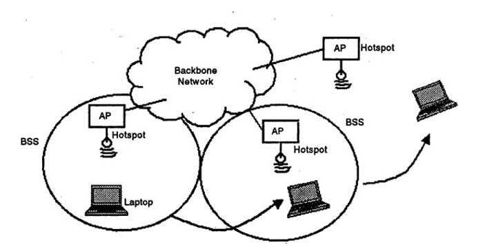
IEEE 802.11 WLAN Architecture
Wireless Access Point (Wi-Fi Hotspot)
IEEE 802.11 (Wi-Fi)
Defined by IEEE in 1997. Specifies protocols for Wireless Local Area Network (WLAN) communication in 2.4 GHz, 5 GHz, and 6 GHz frequency bands.
Transmits data wirelessly using modulated electromagnetic (RF) waves. No cables required between stations and the access point.
Operates at the Physical (PHY) and Data Link (MAC) layers. Upper network layers (IP, TCP, HTTP) are protocol-agnostic to the underlying wireless link.
Supports Infrastructure (AP-based BSS/ESS), Ad-Hoc peer-to-peer (IBSS), and Mesh networking (802.11s) topologies.
IEEE 802.11 in the OSI Model
IEEE 802.11 provides the wireless link layer. Standard Internet protocols (IP, TCP, HTTP) run unchanged on top of it — they are unaware of whether the physical medium is Wi-Fi, Ethernet, or cellular.
Upper sublayer of Layer 2. Provides multiplexing of network protocols, flow control, and error control. Common interface between MAC and Layer 3 (IP).
Controls wireless medium access via CSMA/CA. Handles addressing, ACKs, fragmentation, encryption (WPA3), and QoS.
Converts MAC frames into RF signals (2.4/5/6 GHz, 20–160 MHz channels, OFDM, DSSS, MIMO).
IEEE 802.11 Network Architecture
IEEE 802.11 defines a hierarchical structure connecting wireless stations (STAs) through Access Points (APs) into local cells, which are then interconnected via a Distribution System (DS) to external networks (Internet/Ethernet).
Infrastructure Mode
Infrastructure Mode is the most standard deployment mode for Wi-Fi networks (homes, offices, public hotspots).
- Centralized Control: All communication between stations (STAs) must pass through the Access Point (AP), even if two STAs sit next to each other.
- Wired Gateway: The AP links wireless STAs to the wired backbone infrastructure (Ethernet/Internet).
- Scalability: Easily allows multiple client devices to join and authenticate using a unified SSID and security credentials.
Ad Hoc Network (IBSS)
Ad Hoc mode enables peer-to-peer (P2P) wireless communication directly between stations without needing an Access Point or central router.
- No Central Infrastructure: STAs communicate directly over radio waves within mutual range.
- Temporary Setup: Ideal for quick file sharing, emergency operations, or vehicle-to-vehicle (V2V) communications.
- Distributed Coordination: Beacon generation and timing synchronization are shared among all participating STAs.
Basic Service Set (BSS)
A **Basic Service Set (BSS)** is the fundamental building block of an IEEE 802.11 architecture, consisting of a single Access Point and all associated Stations.
- BSSID: The unique identifier for a BSS, which is the 48-bit MAC address of the Access Point's radio interface.
- Coverage Area (Cell): The geographic area within which stations can maintain radio contact with the AP.
- SSID: The human-readable network name shared by all devices within the service set.
Extended Service Set (ESS)
An **Extended Service Set (ESS)** consists of two or more Basic Service Sets (BSSs) interconnected by a Distribution System (DS).
- Seamless Roaming: Stations can move between AP1 and AP2 without losing connection, as all APs share the same network SSID.
- Distribution Backbone: Wired Ethernet (802.3) or wireless mesh interconnects APs to gateway routers.
- Unified Network: Appears as a single continuous Subnet / LAN to the upper network layers (Layer 3 IP).
Important Terminologies of IEEE 802.11 Architecture
| Term | Description |
|---|---|
| Station (STA) | Any device connected to a Wireless LAN (WLAN). Examples include laptops, smartphones, printers, and wireless access points. |
| Wireless Access Point (WAP) | A wireless router that connects wireless stations to the wired network. |
| Client | A wireless device such as a laptop, computer, smartphone, printer, or IoT device that connects to an Access Point. |
| Access Point (AP) | Acts as a station that provides communication between the wireless medium and the distribution system. |
Stations, Clients and Access Point
IEEE 802.11 Terminologies (Continued)
| Term | Description |
|---|---|
| Distribution System (DS) | Interconnects multiple Basic Service Sets (BSSs) to create an Extended Service Set (ESS). |
| Frame | The MAC Protocol Data Unit (MAC PDU) transmitted over the wireless medium. |
| SSID | Service Set Identifier (Network Name). Devices must use the same SSID to communicate within a WLAN. |
| Portal | Gateway connecting the wireless LAN to external networks such as Ethernet or the Internet. |
.png)
Distribution System connecting multiple BSSs
IEEE 802.11 Data Units and Network Components
| Term | Description |
|---|---|
| SDU | Service Data Unit (SDU) is the input data received by a protocol layer before processing. |
| PDU | Protocol Data Unit (PDU) is the output of a protocol layer containing data and protocol-specific headers. |
| Network Interface Controller (NIC) | Hardware interface (network card) that enables a device to connect to a wired or wireless network. |
Application Data (SDU)
↓
MAC Layer
↓
Frame (PDU)
↓
Physical Layer
↓
Wireless Medium
Service Data Unit (SDU)
- A Service Data Unit (SDU) is the data received by a protocol layer from the layer immediately above it.
- The SDU contains only the payload (user data) and has no protocol header or trailer added by the current layer.
- Each protocol layer treats the received SDU as input for further processing.
- The current layer adds its own control information (headers/trailers) before transmission.
- After encapsulation, the SDU becomes part of the Protocol Data Unit (PDU).
SDU = Input Data to a Layer
Protocol Data Unit (PDU)
- A Protocol Data Unit (PDU) is the data unit transmitted between peer protocol layers.
-
A PDU contains:
- Protocol Header
- User Data (Payload)
- Optional Trailer
- Every protocol layer creates its own PDU by adding protocol-specific control information.
- The PDU produced by one layer becomes the SDU of the next lower layer.
| OSI Layer | PDU Name |
|---|---|
| Application | Message |
| Transport | Segment (TCP) / Datagram (UDP) |
| Network | Packet |
| Data Link | Frame |
| Physical | Bits |
Relationship Between SDU and PDU
⬇
+ Transport Header
⬇
TCP Segment (PDU)
⬇
+ IP Header
⬇
IP Packet (PDU)
⬇
+ MAC Header + Trailer
⬇
Ethernet Frame (PDU)
⬇
Bits on Physical Medium
- The SDU of one layer becomes the payload of the next lower layer.
- Each lower layer adds its own header (and sometimes a trailer).
- This process is called Encapsulation.
- At the receiver, headers are removed layer by layer in a process called Decapsulation.
- The original application data is finally delivered to the destination application.
SDU = Input to a protocol layer
PDU = Output from that protocol layer
IEEE 802.11 Physical Medium Specifications
IEEE 802.11 defines multiple physical layer technologies for wireless communication.
| Technology | Frequency / Medium | Data Rate |
|---|---|---|
| Diffused Infrared (IR) | 850–950 nm | 1–2 Mbps |
| Direct Sequence Spread Spectrum (DSSS) | 2.4 GHz ISM Band | 1–2 Mbps (Up to 7 channels) |
| Frequency Hopping Spread Spectrum (FHSS) | 2.4 GHz ISM Band | 1–2 Mbps |
IEEE 802.11 Standards and ISM Band
The Industrial, Scientific and Medical (ISM) band (2400–2483.5 MHz) is an unlicensed radio spectrum, allowing wireless devices to operate without government licensing.
| Standard | Frequency | Maximum Data Rate | Typical Range |
|---|---|---|---|
| 802.11b | 2.4 GHz | 22 Mbps | 100 m |
| 802.11a | 5 GHz | 54 Mbps | 100 m |
| 802.11g | 2.4 GHz | 54 Mbps | 100 m |
• 2.4 GHz provides wider coverage but experiences more interference.
• 5 GHz offers higher throughput with less interference but a shorter effective range.
IEEE 802.11 MAC Protocol – CSMA/CA
- IEEE 802.11 uses the Carrier Sense Multiple Access with Collision Avoidance (CSMA/CA) protocol for medium access.
- Before transmitting, a station listens to the wireless channel.
- If the channel is idle for a Distributed Inter-Frame Space (DIFS), the station immediately transmits the frame.
- If the channel is busy, the station continues sensing the channel.
- Once the channel becomes free for a DIFS period, the station waits for a random back-off interval before transmitting.
- The random back-off reduces the probability of two stations transmitting simultaneously.
Unlike Ethernet (CSMA/CD), Wi-Fi cannot detect collisions while transmitting. Instead, it attempts to avoid collisions using carrier sensing and random back-off.
IEEE 802.11 MAC Frame Format
The 802.11 MAC layer adds a header to IP packets for wireless transmission. Wi-Fi frames use up to 4 MAC addresses to handle complex routing between access points.
Tells the receiver what type of frame this is, if the packet is encrypted, and where it is going (To/From DS).
- Management: Beacon (AP broadcast), Association (Joining)
- Control: RTS, CTS, ACK (Fast signaling, no data payload)
- Data: Carries actual user internet traffic (IP packets)
802.11 MAC Frame Structure
Frame Control Field Breakdown (16 bits)
- 0 / 0: Ad-hoc (Addr 1=DA, 2=SA, 3=BSSID)
- 1 / 0: STA $\to$ AP (Addr 1=BSSID, 2=SA, 3=DA)
- 0 / 1: AP $\to$ STA (Addr 1=DA, 2=BSSID, 3=SA)
- 1 / 1: AP $\to$ AP (Addr 1=RA, 2=TA, 3=DA, 4=SA)
Hidden Node Problem & RTS/CTS
Stations A and C want to talk to AP B. A and C cannot hear each other. They both think the channel is idle and transmit at the same time, causing a collision at B.
- 1. RTS (Request to Send): A asks B for permission to send.
- 2. CTS (Clear to Send): B shouts "Yes!" to everyone. Even hidden C hears this.
- 3. Wait (NAV): C waits patiently because it heard B's CTS.
- 4. Send Data: A sends data safely without C interfering.
Evolution of IEEE 802.11 Standards
| Generation | IEEE Standard | Release Year | Frequency | Max Data Rate | Key Technologies |
|---|---|---|---|---|---|
| Legacy | 802.11b / a / g | 1999–2003 | 2.4 / 5 GHz | 11 – 54 Mbps | DSSS, OFDM |
| Wi-Fi 4 | 802.11n | 2009 | 2.4 / 5 GHz | 600 Mbps | MIMO (4x4), 40 MHz Channels, Frame Aggregation |
| Wi-Fi 5 | 802.11ac | 2013 | 5 GHz | 3.46 Gbps | MU-MIMO, 256-QAM, 80/160 MHz Channels, Beamforming |
| Wi-Fi 6 / 6E | 802.11ax | 2019 / 2021 | 2.4 / 5 / 6 GHz | 9.6 Gbps | OFDMA, 1024-QAM, Target Wake Time (TWT for IoT) |
| Wi-Fi 7 | 802.11be | 2024 | 2.4 / 5 / 6 GHz | 46 Gbps | 320 MHz Channels, 4096-QAM (4K-QAM), Multi-Link Operation (MLO) |
Bluetooth Technology (IEEE 802.15.1)
A short-range, low-power radio operating in the 2.4 GHz band. Designed to connect mobile devices and smart peripherals (like earbuds or smartwatches).
Constantly jumps between 79 different channels (1600 times/sec) to avoid Wi-Fi interference.
The central device (Master) controls the timing of all peripherals (Slaves).
• Classic Bluetooth: Continuous streaming (e.g., Audio, File Transfers).
• BLE (Low Energy): Short data bursts, ultra-low power (e.g., IoT Sensors).
Bluetooth Network Topology (Piconet & Scatternet)
A simple star network with 1 Master and up to 7 active Slaves.
- The Master controls all timing and channel hopping.
- Slaves only speak when spoken to by the Master.
Created by connecting multiple Piconets together.
- A "Bridge Node" connects them by acting as a Slave in one Piconet and a Master in another.
- Greatly extends the range of the network.
Bluetooth Protocol Stack
Bluetooth Low Energy (BLE) & AI IoT
Designed for ultra-low power consumption. Sensors can operate for years on a tiny coin-cell battery.
- Fast Discovery: Uses 3 dedicated "Advertising" channels so devices can find each other instantly.
- Deep Sleep: Devices stay asleep >99% of the time and wake up in microseconds just to send a tiny burst of data.
- GATT Architecture: Think of data like a menu. Devices offer Services (e.g., Battery) containing Characteristics (e.g., 85%).
8.3 Real-Time Operating Systems (RTOS) for AI
An RTOS guarantees that tasks finish within strict deadlines. For AI (like self-driving cars), getting the answer on time is just as important as getting it right.
Missing a deadline = Total Failure (e.g., Car brakes fail to apply in time). Deadlines must never be missed.
Missing a deadline = Annoying but Safe (e.g., Siri takes 3 seconds to answer instead of 1 second).
RTOS Stack & AI Framework Integration
Running AI on tiny microcontrollers requires specialized engines like TensorFlow Lite Micro that sit right on top of the RTOS kernel.
| RTOS OS | Type | Target AI Hardware |
|---|---|---|
| FreeRTOS | Microkernel | ESP32-S3, STM32, Cortex-M |
| Zephyr RTOS | Modular RTOS | Nordic nRF5340, RISC-V |
| QNX Neutrino | POSIX Microkernel | NVIDIA Drive Orin, Automotive AI |
| VxWorks | Hard RTOS | Aerospace, Robotics Edge AI |
8.4 Scheduling Algorithms for Real-Time AI Tasks
In an RTOS, every recurring AI task is defined by three simple variables:
- $C$ (Computation Time): How long the AI takes to run (e.g., 5ms).
- $T$ (Period): How often the AI needs to run (e.g., every 33ms for a 30 FPS camera).
- $D$ (Deadline): When the answer must be ready by.
If you divide Computation Time by Period ($C/T$), you get how much of the CPU that task needs. If all tasks combined need > 100% of the CPU, the system crashes!
RM vs. EDF Scheduling Algorithms
Tasks with shorter periods ($T_i$) receive higher static priority.
• Schedulability bound: $U \le N(2^{1/N} - 1)$. For $N \to \infty$, $U \approx 69.3\%$.
• Simple, deterministic, standard in FreeRTOS & VxWorks.
Task with the closest absolute deadline ($d_i$) gets highest priority.
• Optimal dynamic algorithm: Schedulable if $U \le 100\%$.
• Higher runtime overhead due to dynamic priority queue updates.
When a low-priority task holds a shared resource (e.g., NPU mutex) needed by a high-priority AI task. Resolved using Priority Inheritance Protocol (PIP) or Priority Ceiling Protocol (PCP).
Comparison: RM vs. EDF
| Parameter | Rate Monotonic (RM) | Earliest Deadline (EDF) |
|---|---|---|
| Priority | Static (1 / Period) | Dynamic (Closest Deadline) |
| Max CPU Util. | ~69.3% ($N \to \infty$) | 100% (Optimal) |
| Overhead | Low (Fast $O(1)$ array) | High (Queue re-sorting) |
| Overload | Predictable (Low priority drops) | Domino effect (Cascade failures) |
| RTOS Support | FreeRTOS, VxWorks, QNX | Linux (SCHED_DEADLINE) |
AI-Specific Real-Time Scheduling Strategies
Because neural networks take a long time to run, standard RTOS scheduling isn't enough. We use clever AI tricks to guarantee deadlines:
If the RTOS deadline is about to hit, the AI stops computing and outputs an "early exit" answer. It's better to be 85% accurate on-time than 99% accurate but too late!
If the system is overloaded, dynamically switch from a heavy model (MobileNet-Large) to a fast/light model (MobileNet-Small) on the fly.
Use the CPU to preprocess images, the NPU to run the AI, and the GPU to draw the boxes on screen—all simultaneously in a pipeline.
Textbooks
- Raj Kamal, Embedded Systems: Architecture, Programming and Design, 3rd Edition, McGraw-Hill Education.
- Frank Vahid & Tony Givargis, Embedded System Design: A Unified Hardware/Software Introduction, John Wiley & Sons.
- Wayne Wolf, Computers as Components: Principles of Embedded Computing System Design, Morgan Kaufmann.
- David E. Simon, An Embedded Software Primer, Addison-Wesley.
- Behrouz A. Forouzan, Data Communications and Networking, 5th Edition, McGraw-Hill.
- Andrew S. Tanenbaum & David J. Wetherall, Computer Networks, 5th Edition, Pearson.
Online References
- IEEE Standards Association
https://standards.ieee.org/ - IEEE 802.11 Working Group
https://www.ieee802.org/11/ - USB Implementers Forum (USB-IF)
https://www.usb.org/ - Components101 – IR Sensor Module
https://components101.com/sensors/ir-sensor-module - Codrey Electronics – RS232 Serial Communication
https://www.codrey.com/embedded-systems/rs232-serial-communication/ - Analog Devices (MAX232 Datasheet)
https://www.analog.com/ - Arduino Documentation
https://docs.arduino.cc/ - Espressif ESP32 Documentation
https://docs.espressif.com/